


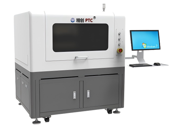
Ultrasonic Scanning Equipment - SAM120
Product Introduction:
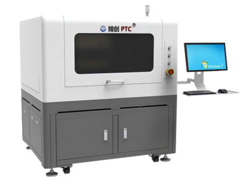
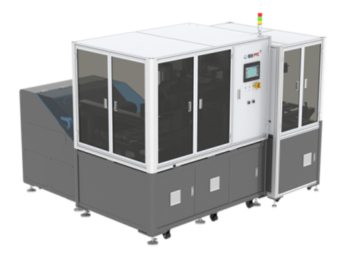
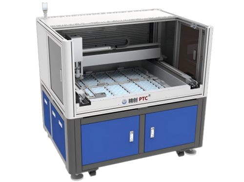
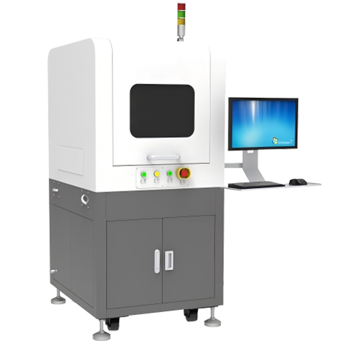
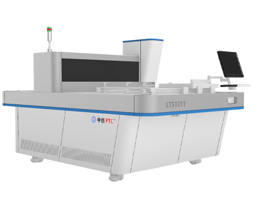
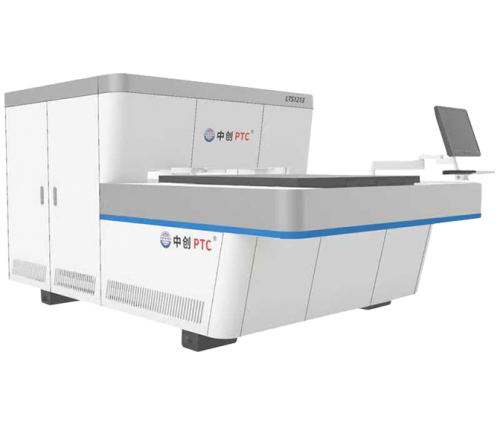
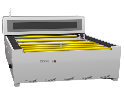
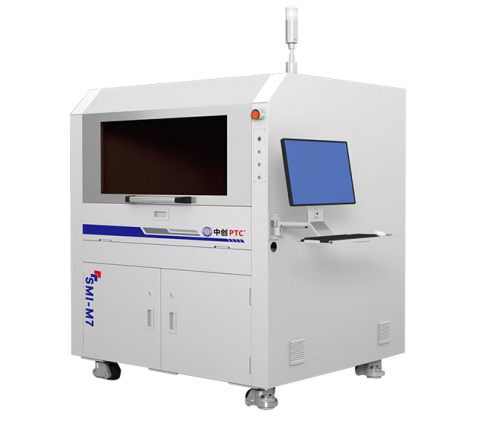
In order to improve the detection efficiency of the power semiconductor industry, our company has developed a semi-automatic ultrasonic non-destructive testing equipment, which mainly targets the detection of voids or bubbles at the joints of various layers of packaged power devices (heat sinks and copper-clad laminates, upper and lower copper surfaces of copper-clad laminates and substrates, chips and upper copper surfaces), and performs automatic marking.


 Home
Home Products
 Telephone
 Message

